Operational edge: Why sliding vanes are a smart spec
When it comes to positive displacement (PD) pumping technologies, gear and sliding vane pumps always have stood out for their reliability and versatility in liquid-handling applications. These two factors alone have made them a popular choice for loading/unloading, transport and metering applications.
Regarding reliability, these pumps are effective at moving liquids from ships, railcars and tank trucks, as well as from process to process within a manufacturing plant or to and from storage tanks or onto transport vehicles, which send the product to bulk storage facilities or end users. On the versatility side, these pumps can handle an extensive range of liquids, such as crude oil, refined fuels, biofuels, chemicals, solvents and raw and finished foodgrade materials.
While these two pump technologies are proficient with fluid-handling tasks, and have been so for decades, sliding vane pumps have multiple benefits that make them the better choice for these applications. Five points of comparison identify the main differences between these two pump technologies.
Pump technologies
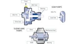
Sliding vane pumps feature a rotor with vanes that slide within it as the rotor turns. This sliding motion creates chambers into which the liquid flows, and as the rotor turns, the liquid moves to the outlet where it is discharged as the pumping chamber compresses. Each revolution of the rotor displaces a constant volume of fluid with little chance for slippage, which is the very essence of a PD pump. Variances in pumping pressure have little effect on the sliding vane pump’s flow rate, and the open flow profile provides a gentle and shear-sensitive environment within the pump.
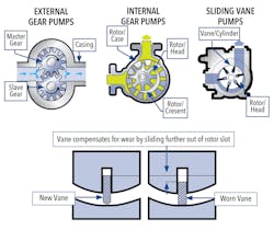
Gear pumps, meanwhile, are available with either external or internal gear designs. They deliver a constant amount of liquid with each revolution of the gears, while their tight clearances and speed of rotation restrict any fluid from moving backward, or “slipping,” during their operation. Since the gears are rigid, the pumps create a smooth, pulse-free flow, but also one that can handle very high pumping pressures, especially those needed when transferring high-viscosity liquids.
Internal clearances
All PD-pump technologies require tight internal clearances to minimize slip and optimize volumetric efficiency. For internal gear pump models, the clearances are tightest where the rotor/case, rotor/head and rotor/crescent mesh, and they are at their tightest when the pump first enters service. However, all of these components—because they constantly contact each other as they rotate—will wear while the pump is in operation.
As the wear increases, tightness decreases, resulting in product slip that will compromise volumetric consistency. For every gallon moving through a gear pump, its efficiency lowers with no chance of improvement. The only remedy for this situation, known as flow degradation or flow erosion, is to replace the pump.
Sliding vane pumps achieve tight clearances where the rotor/ head and vane/cylinder meet, with a brand-new pump having the tightest clearances possible. Unlike gear pumps, though, the contact surfaces self-adjust for wear. The edges of the vanes that contact the cylinder will wear but will continue to slide out of the rotor and stay in constant contact with the cylinder. This means that even after many years and millions of gallons of transferred liquids, internal slip will not occur, guaranteeing volumetric consistency throughout the pump’s lifetime. This is called flow sustainment.
Component life
Gear pump design relies on cantilevered support for its driver and idler gears, much like the support system for an end- suction centrifugal pump. Since the pump load is perpendicular to the cantilevered support for both gears, shaft deflection occurs during operation. This puts strain on the cantilevered support, which opens the door to a whole series of potential operational risks, including:
- Reduction of mechanical seal life because of the difficulty of sealing a moving surface.
- Movement of the seals away from the bearing, which increases deflection at the sealing surface.
- Reduction of shaft life because the shaft is deflected twice during every revolution
This means that a 500-rpm pump will suffer 60,000 deflected load cycles during every hour of operation, which will shorten the life of the shaft. Other component concerns with cantilevered support include idler-pin wear, which affects the clearance relationship between the idler and the rotor gear, resulting in increased wear and reduced flow rates. Another concern is crescent wear, which increases slip and reduces flow.
Sliding vane pumps don’t suffer these detriments because they have a between-the-bearing support design, which means that the rotor is supported equally on both sides, resulting in minimal shaft deflection and the prevention of cyclical deflection and fatigue. Further, the sealing surfaces are immediately adjacent to the bearings (the most stable location), making them stationary and ensuring longer seal life. The ultimate benefit of the between-the-bearing design is that no uneven loads occur, which ensures even wearing of all components.
System functionality
It is unavoidable that gear pumps will have metal-on-metal contact. Because of this, these pumps are not suited for dry-run operation. If the pump runs dry, the metal-on-metal contact will cause galling, which reduces pump longevity and reliability, and increases maintenance costs and downtime.
Since sliding vane pumps do not have metal-on-metal contact, they can run dry without galling or any adverse effects on pump life. Operationally, the dry-run capabilities of sliding vane pumps make them ideal for liquid-transfer applications that feature the following conditions:
- Self-priming: Even if a sliding vane pump starts empty, it is still able to draw a vacuum, compress and push air through the discharge hose and draw liquid from the suction source until the pump is primed, all without damaging the unit.
- Line stripping: The ability to run dry, operate bi-directionally and compress air make sliding vane pumps ideal for product-recovery applications that require the evacuation of piping and hoses. This recovers high-value and hazardous products.
- Tank heel withdraw: The final 10% residual volume within a tank is referred to as the tank heel. Sliding vane pumps effectively remove this liquid heel with each batch, improving both efficiency and profitability.
- Dry run: Dry run is operating a pump without liquid, which occurs accidently (i.e., operator error) and intentionally (i.e., line striping). Sliding vane pumps are robust enough for both accidental and intentional dry run.
- Suction lift: Sliding vane pumps pull undiminished dry vacuum for the life of the pump (in excess of 22 inHg or 0.75 bar). This is ideal for top offload, underground storage or berm applications.
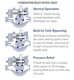
Craking pressure
Gear pumps have a reduced-port linear trim valve, which means they have two valve set points: cracking and full bypass. The full bypass setpoint is limited by the hose, meter, nozzle or other downstream components. The valve begins opening at its separate cracking pressure, recirculating liquid well in advance of the full bypass setpoint. This lowers the capacity of every gear pump and extends delivery times by as much as 30%.
Conversely, sliding vane pumps have a full-port, quick-opening trim valve, meaning one set point covers cracking and full bypass recirculation. The setpoint is optimized to the hose, meter, nozzle or other components’ limits, and the valve does not crack open until it reaches this pressure. This allows truck operators to leverage the full capacity of every pump and maintain fast delivery times.
Liquid sensitivity
Gear pumps rely on a liquid film to prevent metal-on-metal contact damage. Gear pumps prefer viscous liquids with a viscosity greater than 100 centipoise (cP). Thin liquids are not thick enough to create an adequate film.
Gear pumps also have poor solids-handling capability because their meshing operation creates continuous pinch points within the liquid path, which leads to premature gear wear. The meshing gear and crescent in the internal gear model also prevents the handling of liquids with suspended solids. Gear pumps also require lubrication on the gear during operation. Solvents and chemicals, along with other non-lubricating liquids, create problems for gear pumps.
Because sliding vane pumps don’t experience metal-on-metal contact, there is no need for a minimum liquid viscosity. This means these pumps have a liquid-handling range from ultra-thin liquids (0.2 cP) up to liquids with a thickness as high as 22,500 cP, without a decrease in performance when handling thin (3-100 cP) or medium-viscosity (100-5,000 cP) liquids.
Vane pumps also can handle liquids with small particulates up to 40% concentrations. Sliding vane pumps also require no self-lubrication, so lubricating and non-lubricating liquids can be handled effectively. Sliding vane pumps are renowned for operating reliably under applications where multi-phase vapor/liquid mixtures are expected. Imagine using the same pump for condensate and crude oil. Sliding vane pumps are well suited for ultra-low viscosity and non-lubricating applications, as well as thick crude applications with suspended solids.
Final considerations
There are a few areas where gear pumps have the operational edge over their sliding vane counterparts. The efficiency and service life of sliding vane pumps suffer when handling abrasive liquids. The vanes are designed to adjust to 100% efficiency, which greatly accelerates wear. Gear pumps are able to “break in” at a lower operational efficiency, which makes them more tolerant to abrasive liquids.
Temperature thresholds also favor gear pumps, which are compatible with liquids up to 800°F (425°C). Sliding vane pumps can only reach 240°F (115°C), with some models able to handle temperatures as high as 500°F (265°C). Gear pumps also have a higher maximum viscosity rating of 1 million cP, while sliding vane pumps operate best with viscosities ranging from 0.2 to 22,500 cP.
While both pumps have reputations for being workhorses in several industries, sliding vane pumps provide more functionality and higher reliability, making them better suited for applications and systems with a vast range of operating conditions. This is especially true for applications with low-abrasion liquids with viscosities up to 22,500 cP and operating temperatures less than 500°F (265°C).
Geoff VanLeeuwen, P.E., is the director of products and applications for PSG Grand Rapids. He can be reached at [email protected]. For more information on Blackmer’s full line of pumps and compressors, visit blackmer.com.
About the Author
Geoff VanLeeuwen
Geoff VanLeeuwen, P.E., is the director of products and applications for PSG Grand Rapids. He can be reached at [email protected]. For more information on Blackmer’s full line of pumps and compressors, visit blackmer.com.